Diagram Options dialog box
Split Pipelines Around Components
Select this check box to divide a single pipeline into two pipelines when a component, such as a valve, is glued to the pipeline. The shape data in the original pipeline are copied to both pipelines. This check box is selected by default.

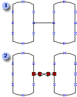
 A pipeline between two vessels.
 When a valve is dropped onto a pipeline, the pipeline is split into two pieces, with both pieces representing the same pipeline component.
Split Pipelines When Branches Are Created
Select this check box to divide a pipeline when another pipeline is glued to it. This results in three pipelines, which are all glued to a junction shape.
This check box is selected by default.

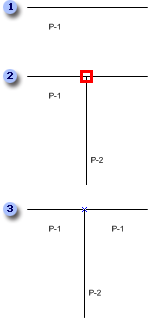
 A section of a pipeline.
 A pipeline connected to another pipeline.
 The original pipeline is split into two pieces, with a junction at the intersection. The junction shape is set to invisible by default.
Use This Shape At Pipeline Branches
Specify the shape to use as a junction shape when pipelines are split. You can specify a shape on the document stencil by clicking the name of the shape on the list or by typing the name of the shape. You can also leave the field blank, in which case an invisible shape will be used.
By default, the Junction shape is selected.
Repair Split Pipelines
Select this check box to replace a split pipeline with a single pipeline when the shape that split the pipeline, such as a valve or other pipeline, is deleted.
This check box is selected by default.

 A pipeline split as a result of adding a valve.
 A single pipeline after deleting the valve.
Number Components When They Are Added To The Drawing
Select this check box to automatically number shapes as they are added to the drawing.
This check box is selected by default.
No comments:
Post a Comment