Create a UML sequence diagram
In Visio, you build Unified Modeling Language (UML) sequence diagrams like any other Visio diagram, by dragging shapes onto the UML Sequence diagram template. The sequence diagram is popular with software designers and IT professionals, but it's also useful in sketching out many kinds of interaction processes.
If you've built UML diagrams in previous versions of Visio, you might remember using modeling or wizards to build the diagrams, which then were locked against editing or formatting. In Visio 2013 and later versions, the shapes are unlocked and more flexible, so you can change their behavior if needed. Drawings are more customizable but still meet the UML 2.4 standard.

To build a sequence diagram, use the UML Sequence template, which includes the UML Sequence stencil. Drag shapes from the stencil onto the drawing canvas to build the diagram.
Using the shapes
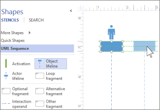
Lifelines Drag Actor lifeline shapes for each participant, and Object lifeline shapes for each system component in your process.
-
To make a timeline longer or shorter, click the dotted time line on a lifeline, then drag the bottom endpoint up or down.
-
Double-click in the heading box for each lifeline to enter a name or title.
Tip: As you drag the lifelines into place, use the green alignment guides to help you line up and space them relative to the other lifeline shapes.
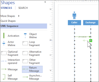
Messages Drag message or interaction shapes to indicate messages or other interaction between the lifelines.
-
Attach the beginning endpoint to the lifeline sending the message, then drag the head endpoint to the lifeline receiving the message.
-
Double-click the message shape to create a text box, and type in the message.
-
Use the Asynchronous Message shape to show when an action might not happen immediately.
Tip: When you drag the message shape onto the drawing canvas, each lifeline shows connection points to help you glue the message endpoints to each lifeline. A green circle appears at the endpoint when it glues to a connection point. The connections points disappear when you are done dragging.
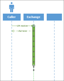
Activation Drag an Activation bar shape to a lifeline to show when that object or participant is active in the process.
-
Drag the endpoints of the Activation bar up or down to make it the length that you want.
Fragments If one or more interactions form a loop, or require a condition to be met to end the interaction, enclose those interactions in a fragment shape.
-
Use the Loop fragment for a basic repeating interaction.
-
Use the Alternative fragment shape for an if-then process or interaction. It has two sections, which lets you show the alternative interaction.
-
Use an Interaction Operand shape to show an interaction that occurs if a condition is met.

-
Drag the fragment shape to the interactions it relates to. Use the sizing handles on the fragment shape to ensure it encloses all of the related interactions.
-
Double-click in the title corner of the fragment shape to add a title or short description of the process enclosed by the fragment. Below the title corner, click the [parameters] prompt if you want to enter the conditions that would end that process.
Microsoft Office Tutorials: Create A Uml Sequence Diagram >>>>> Download Now
ReplyDelete>>>>> Download Full
Microsoft Office Tutorials: Create A Uml Sequence Diagram >>>>> Download LINK
>>>>> Download Now
Microsoft Office Tutorials: Create A Uml Sequence Diagram >>>>> Download Full
>>>>> Download LINK NX