Edit connector lines, arrows, or points
You have a lot of flexibility when it comes to editing and working with connectors. You can edit line weight, style, and curvature, control the look of end points and arrows, make connectors curved, angled or straight, and manage connection points in a variety of ways.
Tip The commands in the Tools group on the Home tab put Visio into a different state or mode, which admittedly can be confusing sometimes. Use the keyboard to conveniently switch between the Pointer Tool  (press Ctrl+1) and Connector
  (press Ctrl+3) tools. Whatever tool you are using, such as Text Block or Connection Point, press Esc several times to return to the Pointer Tool (except in Visio 2010).
Most of this article is relevant for the default Dynamic connector shape which can automatically re-route itself around other shapes. There are some types of connectors, such as most of those available from the More Shapes \ Visio Extras \ Connectors stencil, which do not automatically re-route.
What do you want to do?
Make connectors curved, angled, or straight
You can either change a connector or change the default for new connectors.
Change a connector
-
Select the connector.
-
On the Design tab, in the Layout group, select Connectors, and then select the desired routing style Right-Angle Connector, Straight Connector, or Curved Connector.
-
Alternatively, the right mouse click Action menu of the connector shape also has the options to change the connector routing style.
Change the default for new connectors
-
To make the default connector right-angled, straight or curved:
-
Visio Online Plan 2, 2016, 2013 Deselect all shapes by selecting the page. Select the Design tab, then select the Connectors dropdown menu in the Layout group. Then select Right Angle, Straight Lines or Curved Lines.
-
Alternatively, select the File tab, select Print, select Page Setup, select the Layout and Routing tab, and then in the Appearance list, select Straight or Curved.
-
2010 Select the File tab, select Print, select Print Preview, select Page Setup, select the Layout and Routing tab, and then in the Appearance list, select Straight or Curved.
-
Add arrows or other line ends to a connector
You can add arrows, points, or other line ends to a connector.
-
Select a connector.
-
Do one of the following:
-
Visio Online Plan 2, 2016, 2013 Select the Format Shape option from the right mouse Action menu. Alternatively, on the Home tab, in the Shape Styles group, select Line, and then select Line Options.
-
2010 On the Home tab, in the Shape group, select Line, and then select Arrows.
-
-
Do one of the following:
-
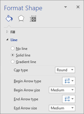
Visio Online Plan 2, 2016, 2013 In the Format Shape pane, under Line, make sure Solid line is selected, and then select the type, size, or cap type.
-
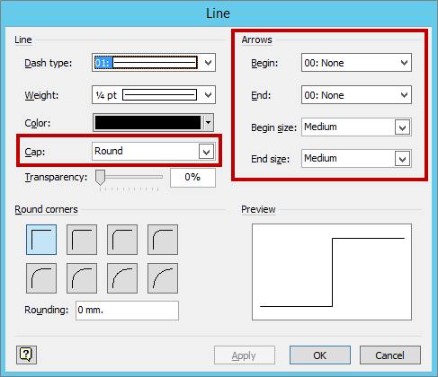
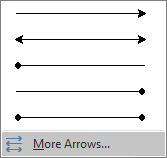
2010 Select More Arrows, in the Line window select the type, size or cap type, and then click OK.
-
Change the weight, style, or curvature of a connector
-
Select a connector.
-
Do one of the following:
-
Visio Online Plan 2, 2016, 2013 Select the Format Shape option from the right mouse Action menu. Alternatively, on the Home tab, in the Shape Styles group, select Line, and then select Line Options.
-
2010 On the Home tab, in the Shape group, select Line, and then select Line Options.
-
-
Do one of the following:
-
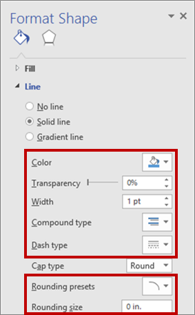
Visio Online Plan 2, 2016, 2013 In the Format Shape pane, under Line, select the weight, style, or curvature.
-
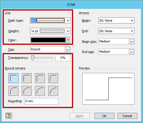
2010 In the Line window, select the weight, style, or curvature, and then click OK.
-
Reverse the direction of a connector arrow
Note: The direction of the connection in some types of diagrams, such as various process flow diagrams, is important. Therefore the Reverse Ends command should be used for these connectors, rather than re-formatting the ends. The Reverse Ends command button can easily be added to your ribbon using the File \ Options \ Customize the Ribbon... feature. This command provides the ability to reverse the flow of all the selected connectors.
Alternatively, to change the direction of a connector, without using the Reverse Ends command, add a new arrow to the end without an arrow and remove the existing arrow from the other end.
-
Select a connector.
-
Do one of the following:
-
Visio Online Plan 2, 2016, 2013 On the Home tab, in the Shape Styles group, select Line, and then select Line Options.
-
2010 On the Home tab, in the Shape group, select Line, and then select Line Options.
-
-
Do one of the following:
-
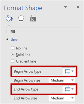
Visio Online Plan 2, 2016, 2013 In the Format Shape pane, under Line, select the:
-
Begin Arrow type and do step 4.
-
End Arrow type and do step 4.
-
-
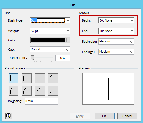
2010 In the Line window select the:
-
Begin Arrow type and do step 4.
-
End Arrow type and do step 4.
-
-
-
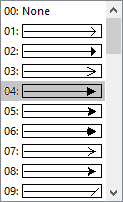
To add, change, or remove an arrow on the beginning and end of the selected connector, select an arrow or None on the arrow menu.
Reroute or intersect connectors
In most cases, you can rely on the default connector behavior. But there are times when you want more control over the routing and intersecting of connectors in your diagram.
Tip Use the Zoom feature to better see small details and to have more fine-point control: Zoom In (press ALT+F6), Zoom Out (ALT+SHIFT+F6), and Fit to Window (CTRL+SHIFT+W).
-
Do one or more of the following:
-
To connect a connector to another connector, add the connector to a shape, and then drag the connector to the other connector.
-
To reroute a connector, select it, and then drag a midpoint to a new location.
-
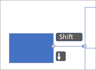
To adjust a connector pixel by pixel, select the connector, and then press Shift+Arrow keys in the direction you want.
-
Note To create a tree diagram, see Create a tree diagram.
More ways to work with connection points
The following sections discuss the many ways you can control connection points.
Tip Use the Zoom feature to better see small details and to have more fine-point control: Zoom In (press ALT+F6), Zoom Out (ALT+SHIFT+F6), and Fit to Window (CTRL+SHIFT+W).
Overview of connection points
A connection point is a special point on a shape that you can "glue" connectors and other shapes to. When you glue a connector or shape to a connection point, they stay connected, even if one of the shapes is moved.
Connection points become visible when you try to connect one shape to another. You see a shape's connection points when you hover near the shape with the Connector Tool or drag the endpoint of any connector or line near a shape that has connection points.
Note Connection points are not the only places you can glue connectors. You can also glue connectors (and lines) to shape vertices, shape handles, and shape geometry. For more information, see Snap & Glue dialog box.
Use point or dynamic connections
There are two types of connections that a connector can have to a shape: a point connection (sometimes referred to as a static connection) or a dynamic connection. You can have either type of connection on either end of a connector. If you use AutoConnect , or the Connect Shapes command, to connect shapes, both ends will have a dynamic connection. If you manually select where a connector is attached to a shape, you can specify the type of connection.
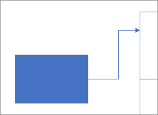
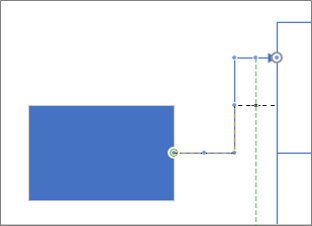
In the following diagram, shape A has a point connection to shape C, and wherever C is moved, the connector from A stays connected to the same point on C. In contrast, shape B has a dynamic connection to C, and the connector from B moves to whichever connection point on C is closest.
Show or hide animation
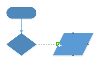
Create a point connection
A point connection keeps a connector glued to a specific point on the shape, even if that shape is moved or rotated.
-
Drag from a connection point on the first shape to a connection point on the second shape.
-
The connector endpoints turn green when the shapes are connected.
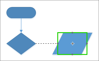
Create a dynamic connection
A dynamic connection allows a connector to change its location on a shape so that, as a shape is moved or rotated, the connector moves to the connection point on the shape that is nearest to the connector's point of origin.
-
Position the Connector Tool over the center of the first shape until a green box appears around the shape.
-
Hold down the mouse button and drag to the center of the second shape.
-
When a green box appears around the second shape, release the mouse button.
Add a connection point to a shape
If the shape you want to glue a connector to does not have a connection point where you want it, you can add one.
-
Select the shape.
-
On the Home tab, in the Tools group, click the Connection Point tool
 .
. -
If connection points are not visible, on the View tab, in the Visual Aids group, select the Connection Points check box.
-
Press Ctrl and click where you want to add a connection point. The new connection point is automatically selected after you place it.
-
On the Home tab, in the Tools group, click Pointer Tool
to return to normal editing.
Move a connection point on a shape
If you're not happy with where a connection point is located, you can move it.
-
Select the shape.
-
On the Home tab, in the Tools group, select the Connection Point tool
. -
If connection points are not visible, on the View tab, in the Visual Aids group, select the Connection Points check box.
-
Press Ctrl and drag the connection point you want to move.
-
On the Home tab, in the Tools group, click Pointer Tool
to return to normal editing.
If you're having a hard time moving the connection point to exactly where you want it, try different snap settings. For more information, see Adjust snap strength or turn snap off.
Delete a connection point
Sometimes a connection point gets in the way. In this case, you can delete it.
-
Select the shape with a connection point that you want to delete.
-
On the Home tab, in the Tools group, click the Connection Point tool .
-
If you don't see any connection points, on the View tab, in the Visual Aids group, select the Connection Points check box.
-
Click the connection point you want to delete. The connection point turns magenta.
-
Press Delete.
-
On the Home tab, in the Tools group, click the Pointer Tool
to return to normal editing.
Hide connection points
Sometimes you want to hide connection points to better view your diagram.
-
On the View tab, in the Visual Aids group, clear the Connection Points check box.
Add text next to a connection point
You can't add text directly on a connection point. You can, however, add text to the shape, and then move the text next to the connection point.
-
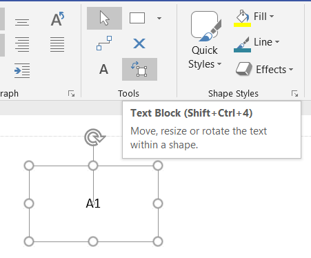
Select the shape where you want to add text, and start typing. The text you type appears in the shape.
-
Select the Home \ Tools \ Text Block tool
 ( Ctrl + Shift + 4 ) The
 -
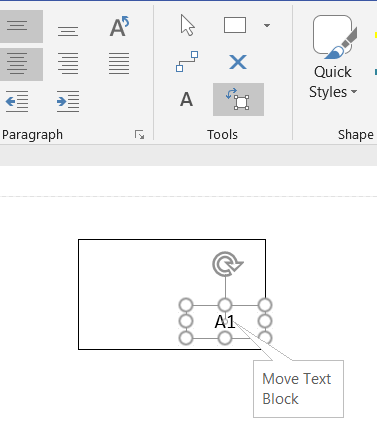
The text block will now be selected
-
Drag the text block to move it and resize as necessary
Select the Pointer Tool ( Ctrl + 1 ) when you want to exit the Text Block tool
An alternative approach is to create multiple uniquely labelled shapes, each with a single connection point, and then group them together to make a larger shape. The connection points will still be usable.
Make a connection point inward, outward, or both
Use inward and outward connection points to control how to attract connector endpoints on shapes.
-
Select the shape.
-
On the Home tab, in the Tools group, click the Connection Point tool
. -
If connection points are not visible, on the View tab, in the Visual Aids group, select the Connection Points check box.
-
If you want an outward or inward & outward connection point, right-click the connection point and click:
-
Inward Most of the time, you want an inward connection point. An inward connection point attracts the endpoints on connectors and the outward connection points and inward & outward connection points on two-dimensional (2-D) shapes.
-
Outward If you have a 2-D shape that you want to glue to another shape, you want an outward connection point. An outward connection point is attracted to inward connection points.
-
Inward & Outward If you have a shape and you don't know how you want it to be glued to other shapes, you probably want an inward & outward connection point.
-
Work with connection points
The following sections discuss the many ways you can control connection points.
Overview of connection points
A shape with four connection points.
Add connection points
If the shape you want to glue a connector or shape to doesn't have a connection point where you want it, it's easy to add one.
-
If connection points are not visible, on the View menu, click Connection Points.
-
Select the shape.
Note: If you don't select the shape first, you can't add a connection point to it. The shape is selected shape if it has a green, dashed border around it.
-
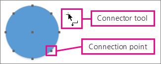
Click the Connection Point tool
.If you don't see the Connection Point tool, click the down arrow next to the Connector tool
, and then click the Connection Point tool . -
Press CTRL and click where you want to add a connection point.
-
If you want an outward or inward & outward connection point, right-click the connection point and click Inward, Outward, or Inward & Outward.
-
Most of the time, you want an inward connection point. An inward connection point "attracts" the endpoints on connectors and the outward and inward & outward connection points on two-dimensional (2-D) shapes.
-
If you have a 2-D shape that you want to glue to another shape, you want an outward connection point. An outward connection point is "attracted to" inward connection points.
-
If you have a shape and you don't know how you want it to be glued to other shapes, you want an inward & outward connection point.
-
-
Click the Pointer tool
 to return to normal editing.
Add text next to a connection point
Unfortunately, you can't add text directly to a connection point. You can, however, add text to the shape and then move the text next to the connection point.
-
Select the shape.
-
Start typing. The text you type appears in the shape.
-
Click the Text Block tool
 .
.If you don't see the Text Block tool, click the down arrow next to the Text tool
 , and then click the Text Block tool .
 -
Drag your text.
Tip: If the shape has a control handle  , you might be able drag it to move shape text quickly.
Move connection points
If you're not happy with where a connection point is located, you can move it.
-
Select the shape.
Note: If you don't select the shape first, you can't move the connection point. The shape is selected shape if it has a green, dashed border around it.
-
Click the Connection Point tool
.If you don't see the Connection Point tool, click the down arrow next to the Connector tool
, and then click the Connection Point tool . -
Drag the connection point you want to move.
If you don't see any connection points, on the View menu, click Connection Points.
-
Click the Pointer tool
to return to normal editing.
If you're having a hard time moving the connection point to exactly where you want it, try different snap settings:
-
On the Tools menu, click Snap & Glue, and then on the General tab, under Snap to, select the options you want.
Delete or hide connection points
Sometimes connection points can get in the way. When they do, you have two choices: delete them or hide them.
To delete a connection point on shape
-
Select the shape.
Note: If you don't select the shape first, you can't delete the connection point. The shape is selected shape if it has a green, dashed border around it.
-
Click the Connection Point tool
.If you don't see the Connection Point tool, click the down arrow next to the Connector tool
, and then click the Connection Point tool . -
Click the connection point you want to delete. The connection point turns magenta.
If you don't see any connection points, on the View menu, click Connection Points.
-
Press DELETE.
-
Click the Pointer tool
to return to normal editing.
To hide a connection point
-
On the View menu, click Connection Points.
Add arrows or other line ends to a connector
You can add elements such as arrows, points, or other line ends to a connector.
-
Select a connector.
-
On the Format menu, click Line.
-
Under Line ends, choose the type and size of line end that you want.
-
Click OK.
Tip: You can also use the Line Ends tool on the Formatting toolbar.
Make connectors curved, angled, or straight
Change a connector on the diagram
-
Right-click the connector.
-
Click Right-Angle Connector, Straight Connector, or Curved Connector.
Note You cannot add handles to straight or right-angle connectors, but you can use the Pencil tool  to add handles to curved connectors.
Change the default for new connectors
-
To make the default connector straight or curved, on the File menu, click Page Setup, click the Layout and Routing tab, and then in the Appearance list, click Straight or Curved.
Reverse the direction of a connector arrow
If you want to change the direction of a connector, you do so by adding a new arrow to the end without an arrow and removing the existing arrow from the other end.
-
Select the connector that you want to change.
-
On the Home tab, in the Shape group, click Line, and then point to Arrows to open the Arrows menu.
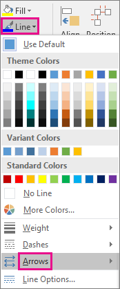
-
At the bottom of the Arrows menu, click More Arrows.
Visio displays the Format Shape task pane with Line expanded.
-
To add, change, or remove an arrow on the beginning of the selected connector, select an arrow or None on the arrow menu for Begin Arrow type.
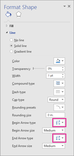
The arrow menus show the currently selected arrow style or None for the selected connector.
-
To add, change, or remove an arrow on the end of the selected connector, select an arrow or None on the arrow menu for End Arrow type.
See Also
Add or remove connector line jumps
All you need to know about Visio desktop connectors (Visio team blog)
No comments:
Post a Comment