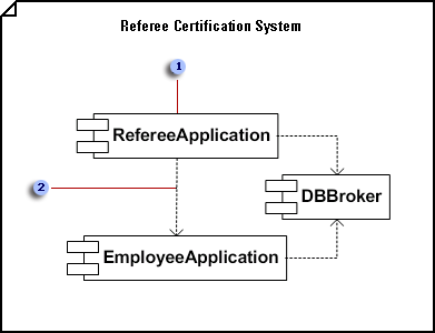
Create a UML component diagram

 In a component diagram, components are generic types rather than instances. To show component instances, use a deployment diagram.
 Dependencies indicate that a client component is dependent upon a supplier component in some way.
-
On the File menu, point to New, point to Software, and then click UML Model Diagram.
-
In the tree view, right-click the package or subsystem in which you want to include the component diagram, and then on the New menu, click Component Diagram.
A blank page appears, and the UML Component stencil becomes the top-most stencil. The workspace displays 'Component' as a watermark. An icon representing the diagram is added to the tree view.
Note: If the tree view isn't visible, point to View on the UML menu, and then click Model Explorer.
-
Drag a Component shape onto the drawing page for each component you want to represent.
-
Where appropriate, drag an Interface shape onto the drawing page and glue the endpoint without the circle to a component shape.
Add an interface to a class, component, or other elements
-
In a static structure, component, or deployment diagram, drag the lollipop Interface shape onto the drawing page.
-
Glue the endpoint without the circle to a connection point
 on the class component, or other element.
 -
Double-click the Interface shape to add a name, operations, and other property values.
tiplist
You can also represent an interface with a rectangular Interface shape that resembles a class. Use this shape when you want to display a list of the interface operations.
To change the type of shape that displays for an interface, right-click the Interface shape and click Show as Class-like Interface or Show as Lollipop Interface.
-
-
Use Dependency shapes to indicate the relationships between components or between one component and another component's interface.
Indicate a dependency relationship between UML elements
-
Drag a Dependency shape from the UML Static Structure, UML Deployment, or UML Component stencil onto the drawing page and place it near the elements you want to relate.
-
Glue the endpoint with an arrowhead to a connection point
 on the element the other element depends on. Glue the endpoint without an arrowhead to a connection point on the element that depends on the other element.
 -
Double-click the dependency to add a name, stereotype, and other properties.
Tip: If you want to indicate a trace, refinement, usage, or binding dependency, you can use the Trace, Refinement, Usage, or Binding shapes from the UML Static Structure stencil.
-
-
Double-click any shape to open its UML Properties dialog box where you can add a name, attributes, operations, and other properties.
-
Save the diagram.
No comments:
Post a Comment