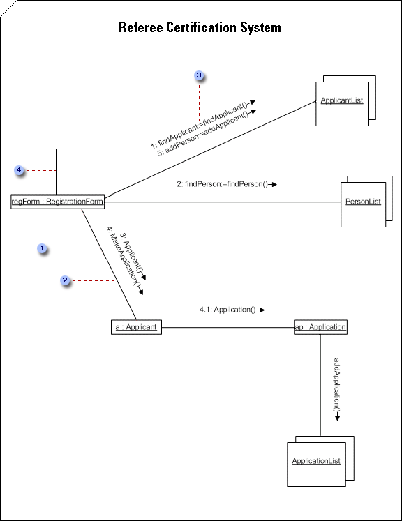
About UML collaboration diagrams
A collaboration diagram represents a collaboration, which is a set of object roles related in a particular context, and an interaction, which is the set of messages exchanged among the objects to achieve an operation or result. It is an interaction diagram that shows, for one system event defined by one use case, how a group of objects collaborate with one another.
Unlike a sequence diagram, a collaboration diagram shows relationships among object roles and it does not express time as a separate dimension. Therefore, the messages in a collaboration diagram are numbered to indicate their sequence.

 In a Classifier Role shape, the object's designator string is underlined to indicate that the object is an instance. You can also include the object name before the colon.
 Links, or AssociationRole, indicate relationships and, with arrowheads, can also indicate navigability.
 Double-click a link, then click Message to define a message that flows along a link. Number procedure messages in accordance with call nesting.
 The first message always comes from outside the context you are including in the diagram.
No comments:
Post a Comment