Add connectors between shapes
Visio makes it easy to connect shapes in your drawing. You can use AutoConnect to connect shapes as you add them, and you can connect existing shapes by using the Connector tool. You can also change the shapes that appear in the mini toolbar and turn AutoConnect on or off.
Connect shapes already on the page
Connect to a shape on another page
Use themes to change connector appearance
Use alternative connector shapes
Change the shapes in the AutoConnect mini toolbar
Automatically connect a shape
One way to connect shapes is to let Visio connect them automatically when you add shape to a page. This is especially convenient when you are creating a flowchart.
-
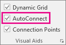
Make sure that AutoConnect is active. On the View tab, in the Visual Aids group, verify that AutoConnect is selected.
-
Drag a shape from the Shapes pane to the page.
-
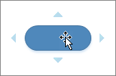
Hold the pointer over the shape until AutoConnect arrows appear around the shape.
-
Hold the pointer over the arrow in the direction you want to add a shape.
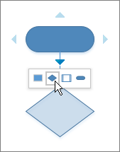
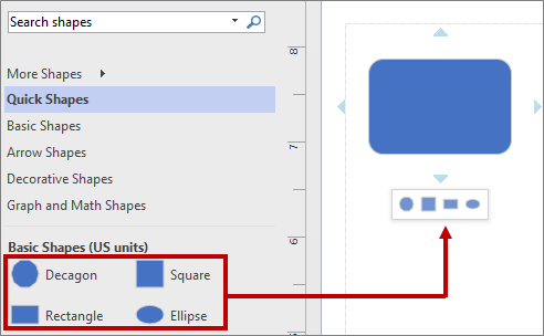
A mini toolbar appears that contains the first four Quick Shapes that are currently in the Quick Shapes stencil. When you point at a shape on the toolbar, Visio displays a preview of that shape on the page.
-
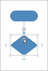
Click the shape you want to add.
-
If you want to continue, point to an AutoConnect arrow on a newly added shape to add another shape that will also be automatically connected.
Connect shapes already on the page
Tip: The commands in the Tools group on the Home tab put Visio into a different state or mode, which admittedly can be confusing sometimes. Use the keyboard to conveniently switch between the Pointer Tool  (press Ctrl+1) and Connector
  (press Ctrl+3) tools. Whatever tool you are using, such as Text Block or Connection Point, press Esc several times to return to the Pointer Tool.
-
On the Home tab, in the Tools group, click Connector
or press Ctrl+3. -
Click a shape and drag a connector to another shape.
-
When you're done, click Pointer Tool
on the Home tab in the Tools group or press Ctrl+1.
Show or hide animation
Alternately, the Connect Shapes command can be added to your ribbon and used to connect multiple shapes in the order they were selected.
Tip: Useful commands that are not already visible in your ribbon can be added by clicking File > Options > Customize the Ribbon.
Connect to a shape on another page
You can only use connectors between shapes on the same page. To connect to a shape on another page, use the Off-page Reference shape to create a hyperlink from one page to the next, or add a Hyperlink and Double-click action to any shape so it can navigate to a different page in the same document.
Use Off-page Reference
-
Open the Basic Flowchart Shapes stencil, and then drag the Off-page reference shape on the current page.

-
In the Off-page reference dialog box, select OK to add the shape to the current page and a newly-created page.
-
On the new page, continue to create your diagram.
-
To change the appearance of the Off-page reference shape, right-click the shape and then select Outgoing, Incoming, Circle, or Arrow.
To move between pages, double-click the Off-page reference shape on either page. For more information, see Off-Page Reference dialog box.
Use Hyperlink and Double-Click
-
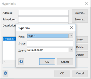
Right-click any shape or press CTRL+K, and then select Hyperlink.
-
Click Browse next to the Sub-address field, and then click the drop-down list next to Page to select the page you want.
Note: The name of a shape on the destination page can also be specified for a hyperlink. Click the Developer tab, and then select Shape Name Use the default name in the Name field, or edit it and then click OK.
-
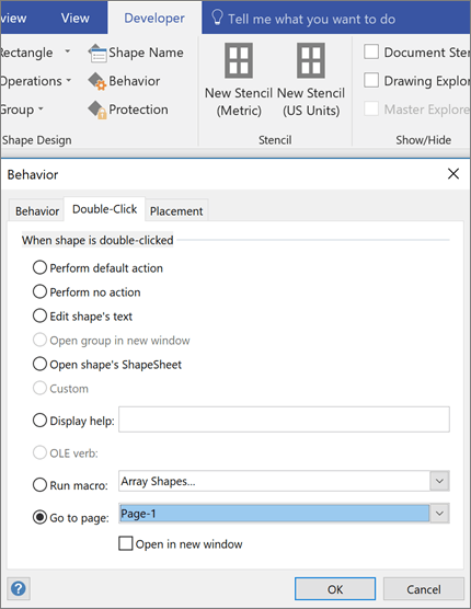
To set the double-click action for a shape, click the Developer tab, and then select Behavior.
-
Click the Double-Click tab, select the Go to page option, and then click the drop-down list to select the page you want.
Note: Do this only after you have edited your page names because they do not get updated here automatically.
Use themes to change connector appearance
While the default appearance of connectors may be simple lines, they may be designed to work with themes that adds embellishments, such as arrow heads. The built-in themes can be applied from the Themes gallery in the Design tab.
Show or hide animation
Notes:
-
To see more embellishments, click the Design tab. In the Variants group, click the drop-down arrow, and then select Connectors.
-
Use alternative connector shapes
Any connector shapes, such as those available on the More Shapes > Visio Extras > Connectors stencil can be used to connect shapes together rather than using the default Dynamic connector shape. These connector shapes can be dragged and dropped on to a page, selected for use with the Connector and Connect Shapes tools, or simply used to replace existing connectors.
-
Open the stencil that contains the alternative connector shapes.
-
Select the existing connectors on the page to be replaced.
-
On the Home tab in the Editing group, click Change Shape, and then select the connector shape you want.
Show or hide animation
Note: The Change Shape feature was introduced in Visio 2013, but the Connector and Connect Shapes tools were introduced prior to Visio 2007.
Change the shapes in the AutoConnect mini toolbar
The shapes on the mini toolbar come from the Quick Shapes stencil of a diagram. The mini toolbar displays up to four shapes. You can customize the shapes that appear on the mini toolbar. The following procedure uses the Basic Diagram as an example.
-
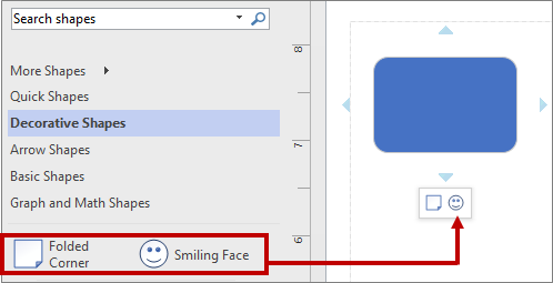
By default, the shapes in the mini toolbar are the first four in the stencil that immediately follows the Quick Shapes stencil. For example, these are the first 4 shapes in the Basics stencil.
-
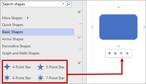
To display different shapes in the mini toolbar for a certain stencil, you can reorder the shapes by dragging them to the top of the stencil. For example, you can drag the 4-point Star, 5-point Star, 6-point Star, and 7-point Star shapes to the top of the Basics stencil.
-
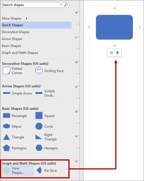
You can also change the order of the stencils by dragging them higher or lower in the Shapes pane. A subset of these shapes appears in the Quick Shapes stencil, and in the same order as they are in the Shapes Pane. For example, after dragging the Decorative Shapes stencil immediately after the Quick Shapes stencil in the Shapes pane, the sequence changes in the Quick Shapes stencil.
Note: When you close and reopen a diagram, the default order of stencils in the Shapes pane is automatically restored and reflected in the Quick Shapes.
-
To use a different stencil as the basis for the mini toolbar, in the Quick Shapes stencil select a shape in the subset of these shapes for a stencil. For example, select Venn Diagram in the Graphic and Math Shapes stencil.
Tip: To return to the default sequence of shapes in a stencil, right-click the stencil name in the Shapes pane, and then select Reset Stencil.
Note: Not all stencils have shapes that can be used in the mini toolbar. For example, the shapes in the Arrow Shapes stencil do not appear on the mini toolbar.
Turn AutoConnect on or off
You can activate and deactivate AutoConnect for the current drawing or as a default for all Visio drawings.
Turn AutoConnect on or off in the active diagram
-
On the View tab, in the Visual Aids group, select or clear AutoConnect.
If the AutoConnect check box is not available, check whether AutoConnect has been turned off for all diagrams by performing the following procedure.
Turn AutoConnect on or off in all diagrams
-
Click the File tab, and then click Options.
-
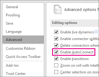
In Visio Options, click Advanced.
-
Under Editing options, select Enable AutoConnect to activate AutoConnect. Clear the AutoConnect check box to deactivate AutoConnect.
-
Click OK.
Connect shapes using AutoConnect
One way to connect shapes is to let Visio connect them automatically when you add shapes to a drawing. This is especially convenient when you are creating a flowchart.
Use the following procedure to add a shape to your drawing that Visio automatically connects to an existing shape.
Use AutoConnect while dragging shapes onto the page
-
Drag a shape from a stencil onto the drawing page and position it near another shape.
-
While still holding down the mouse button, move the pointer over one of the blue triangles. The triangle turns dark blue.
-
Release the mouse button. The shape is placed on the drawing page, and a connector is added and glued to both shapes.
Tip: If you don't like dragging shapes, you can achieve the same result by first selecting a shape in the stencil, resting the pointer over a shape in your drawing, and then clicking one of the blue triangles that appear near that shape.
Use AutoConnect with shapes already on the page
-
Rest the pointer over the shape that you want to connect from.
-
Position the pointer over the blue triangle that is closest to the shape that you want to connect to.
The triangle turns dark blue, and a red box appears around the shape that you want to connect to.
Note: If a red box does not appear around the shape that you want to connect to, the shape may be too far away. Move the shape closer and try again, or use the Connector tool.
-
Click the blue triangle. A connector is added and glued to both shapes.
Enable or disable AutoConnect
You can enable or disable the AutoConnect feature in all Visio drawings, or in only the current drawing. For all drawings:
-
On the Tools menu, click Options.
-
Click the General tab.
-
Under Drawing window options, select the Enable AutoConnect check box.
For the current drawing only:
-
On the Standard toolbar, click the AutoConnect tool.
Note: If clicking the AutoConnect tool does not enable AutoConnect, make sure the Enable AutoConnect check box is selected in the Options dialog box.
Connect shapes using the Connector tool
One of the most flexible ways to add and glue a connector is to draw it by using the Connector tool on the Standard toolbar.
-
Click the Connector tool
on the Standard toolbar. -
Do one of the following:
-
To keep the connector glued to a specific point on a shape, drag from a connection point
 on the first shape to a connection point on the second shape. The connector endpoints turn red when the shapes are connected. This is called a point-to-point connection. With a point-to-point connection, the connector stays glued to the same connection points when you move one of the shapes.
 -
To allow the connector to move to the closest available connection point, position the Connector tool over the center of the first shape until a red box appears around the shape. Hold down the mouse button and drag to the center of the second shape. When a red box appears around the second shape, release the mouse button. This is called a shape-to-shape connection. With a shape-to-shape connection, the connector stays glued to each shape by moving to the closest available connection points when you move either one of the shapes. If no connection points are present, the connector moves to the closest sides.
Note: You can also create connections between shapes where one end of the connector is connected to a connection point and the other end of the connector is connected to the shape (and vice versa).
-
-
Click the Pointer tool
 on the Standard toolbar to return to normal editing.
Notes:
-
To add a connector from one shape to multiple shapes, you need to add multiple connectors; there is no "branching" connector shape.
-
If you are trying to create a point-to-point connection and having a difficult time gluing a connector exactly where you want it, try different snap and glue settings:
-
On the Tools menu, click Snap & Glue, and then on the General tab, select the options that you want.
If you glue to shape geometry, a shape handle, or a shape vertex, a connection point is automatically added if one didn't already exist.
-
Switch between shape and point connections
You can glue connectors from one point on a shape to another point on a different shape, or from an entire shape to another entire shape. You can also create connections in which one end of the connector is glued to a point on a shape and the other end of the connector is glued to an entire shape.
-
Drag a connector end point away from the shape.
-
Do one of the following:
-
To glue an endpoint of the connector to a connection point on a shape, drag the endpoint to one of the shape's connection points until a red box appears around the connection point.
-
To glue an endpoint of the connector to the entire shape, drag the endpoint toward the middle of the shape until a red box appears around the entire shape.
-
No comments:
Post a Comment