Create an SDL flowchart
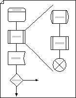
Use Specification and Description Language (SDL) shapes, designed to International Telecommunications Union standards, to create object-oriented flowcharts that document communications and telecommunications systems networks.

-
On the File menu, point to New, point to Flowchart, and then click SDL Diagram.
-
For each step in the process you are documenting, drag a flowchart shape onto your drawing.
-
Connect the shapes.
-
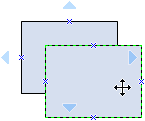
Drag a shape from a stencil onto the drawing page and position it near another shape.

-
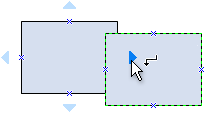
While still holding down the mouse button, move the pointer over one of the blue triangles. The triangle turns dark blue.

-
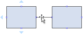
Release the mouse button. The shape is placed on the drawing page, and a connector is added and glued to both shapes.

Tip: To reverse the direction of the arrow on a connector, on the Shape menu, point to Operations, and then click Reverse Ends.
-
-
To add text to a shape, select it, and then type. When you are finished typing, click outside the text block.
-
You can number the shapes in your flowchart to illustrate the sequence of process steps.
-
In a flowchart, select the shapes you want to number.
-
On the Tools menu, point to Add-Ons, and then click Number Shapes.
-
On the General tab, under Operation, click Auto Number. Under Apply To, click Selected Shapes, and then click OK.
Tip: To number new flowchart shapes as they are dragged onto the page, in the Number Shapes dialog box, click Continue numbering shapes as dropped on page.
-
No comments:
Post a Comment