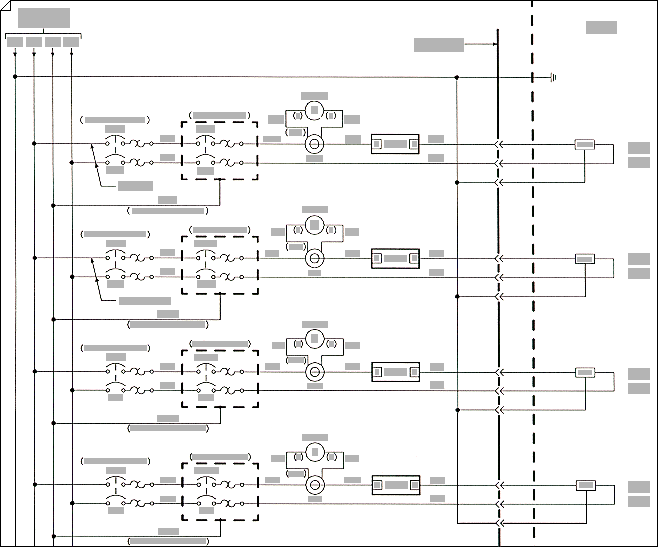
Use the Electrical Engineering drawing type in Visio Professional or Visio Plan 2 to create electrical and electronic schematic diagrams.

-
On the File tab, click New, and then search for Engineering templates.
-
Click one of the following:
-
Basic Electrical
-
Circuits and Logic
-
Fluid Power
-
Industrial Control Systems
-
Parts and Assembly Drawing
-
Piping and Instrumentation Design
-
Plumbing and Piping Plan
-
Process Flow Diagram
-
Systems
-
TQM diagram
-
Work Flow Diagram
-
-
Choose Metric Units or US Units, and then click Create.
The template opens an unscaled drawing page in portrait orientation
 . You can change these settings at any time.
 -
Drag electrical component shapes onto the drawing page. Shapes can have data. You can enter shape data and add new data to a shape.
Enter shape data
-
Select a shape, right-click, click Data, and then click Define Shape Data.
-
In the Define Shape Data dialog box, click in each item and type or select a value.
-
-
Use the Connector tool
 to connect electrical components or connector shapes.
Use the Connector tool
-
Click the Connector tool
 .
. -
Drag from a connection point
 on the first shape to a connection point on the second shape. The connector endpoints turn red when the shapes are connected.
Use connector shapes
-
Drag a connector shape onto the drawing page.
-
Place the connector's begin point
 on the parent shape (the shape you're connecting from).
 -
Place the connector's end point
 on the child shape (the shape you're connecting to).
When the connector is glued to the shapes, the endpoints turn red.
-
-
Label individual electrical component shapes by selecting the shape and typing.
Want More?
Find sample electrical engineering Visio templates and diagrams
-
On the File tab, click New, and then under Template Categories, click Engineering.
-
Click one of the following:
-
Basic Electrical
-
Circuits and Logic
-
Fluid Power
-
Industrial Control Systems
-
Parts and Assembly Drawing
-
Piping and Instrumentation Design
-
Process Flow Diagram
-
Systems
-
-
Choose Metric Units or US Units, and then click Create.
The template opens an unscaled drawing page in portrait orientation
 . You can change these settings at any time.
 -
Drag electrical component shapes onto the drawing page. Shapes can have data. You can enter shape data and add new data to a shape.
Enter shape data
-
Select a shape, right-click, click Data, and then click Define Shape Data.
-
In the Define Shape Data dialog box, click in each item and type or select a value.
-
-
Connect electrical components using the Connector tool
 or connector shapes.
Use the Connector tool
-
Click the Connector tool
 .
. -
Drag from a connection point
 on the first shape to a connection point on the second shape. The connector endpoints turn red when the shapes are connected.
Use connector shapes
-
Drag a connector shape onto the drawing page.
-
Place the connector's begin point
 on the parent shape (the shape you're connecting from).
 -
Place the connector's end point
 on the child shape (the shape you're connecting to).
When the connector is glued to the shapes, the endpoints turn red.
-
-
Label individual electrical component shapes by selecting the shape and typing.
-
On the File menu, point to New, point to Engineering, and then click one of the following:
-
Basic Electrical
-
Circuits and Logic
-
Industrial Control Systems
-
Systems
These templates open an unscaled drawing page in portrait orientation
 . You can change these settings at any time.
 -
-
Drag electrical component shapes onto the drawing page. Shapes can have data. You can enter shape data and add new data to a shape.
Enter shape data
-
Select a shape, and then on the Shape menu, click Shape Data.
-
In the Shape Data dialog box, click in each item and type or select a value.
-
-
Connect electrical components using the Connector tool
 or connector shapes.
Use the Connector tool
-
Click the Connector tool
 .
. -
Drag from a connection point
 on the first shape to a connection point on the second shape. The connector endpoints turn red when the shapes are connected.
Use connector shapes
-
Drag a connector shape onto the drawing page.
-
Place the connector's begin point
 on the parent shape (the shape you're connecting from).
 -
Place the connector's end point
 on the child shape (the shape you're connecting to).
When the connector is glued to the shapes, the endpoints turn red.
-
-
Label individual electrical component shapes by selecting the shape and typing.
No comments:
Post a Comment