Create a UML use case diagram
You can use Visio to build Unified Modeling Language (UML) use case diagrams. Unified Modeling Language (UML) is a standard way to draw software models.

 Defining the system boundary determines what is considered external or internal to the system.
 An actor represents a role played by an outside object. One object may play several roles and, therefore, is represented by several actors.
 A communicates relationship illustrates the participation of the actor in the use case.
 A use case is a set of events that occurs when an actor uses a system to complete a process. Normally, a use case is a relatively large process, not an individual step or transaction.
-
On the File tab, point to New, and then open a blank diagram.
-
Click More Shapes > Software and Database > Software > UML Use Case.
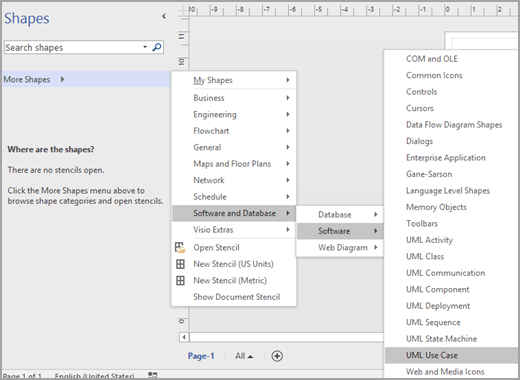
-
To indicate a subsystem in a use case diagram
-
Drag a Subsystem shape onto the drawing page. The subsystem can represent your entire system or a major component.
-
Double-click the Subsystem shape, and then type a new name for the for it, or press the DELETE key to delete the existing name. Click outside the shape on the drawing page.
-
To resize the subsystem, select the shape, and then drag a selection handle.
-
-
Drag Use Case shapes from the Use Case stencil and place them inside the subsystem boundary, and then drag Actor shapes to the outside of the subsystem boundary.
-
Use connector shapes to indicate relationships between use cases and actors. There are five connectors available:
-
Association: Shows the relationship of an actor to a use case.
-
Dependency: Indicates that one use case has a dependency on another.
-
Generalization: Indicates that a use case is a specific way to achieve goals of the general use case.
-
Include: Shows how a use case is broken into smaller steps.
-
Extend: Shows that one use case adds functionality to another.
Example: To indicate a relationship between an actor and a use case
-
In a use case diagram, drag an Association connector shape onto the drawing page.
-
Glue one endpoint of the Association shape to a connection point on an Actor shape. Glue the other endpoint to a connection point on a Use Case shape.
-
-
Save the diagram.
See also
For more information about use case diagrams (and procedures for using Microsoft Visual Studio to create use case diagrams), go to UML Use Case Diagrams: Reference.
-
On the File tab, point to New.
-
Under Template Categories, click Software and Database.

-
Click UML Model Diagram. A blank drawing page appears.

-
In the tree view, right-click the package or subsystem in which you want to include a use case diagram, then point to New, and then click Use Case Diagram.
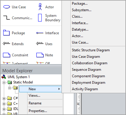
A blank page appears, and the UML Use Case stencil becomes the top-most stencil. An icon representing the diagram is added to the tree view.
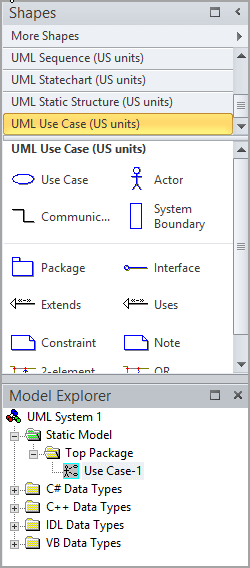
Note: If the tree view is not visible, on the UML tab, in the Show/Hide group, select Model Explorer.
-
To indicate a System Boundary in a use case diagram
-
Drag a System Boundary shape onto the drawing page.
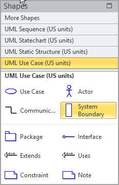
-
Double-click the System Boundary shape, and then type a new name for the system or press the DELETE key to delete the existing name. Click outside the shape on the drawing page.
-
To resize the system boundary, select the shape, and then drag a selection handle.
-
-
Drag Use Case shapes from the Use Case stencil and place them inside the system boundary, and then drag Actor shapes to the outside of the system boundary.
-
Use Communicates shapes to indicate relationships between use cases and actors.
To indicate a relationship between an actor and a use case
-
In a use case diagram, drag a Communicates shape onto the drawing page.
-
Glue one endpoint
 of the Communicates shape to a connection point
  on an Actor shape. Glue the other endpoint to a connection point on a Use Case shape.
 -
If you want to add an arrow to indicate the flow of information, do the following:
-
Double-click the Communicates shape, then, under Association, click the end you want to edit, and then click Properties.
-
In the Association End category, check IsNavigable, click OK, then click OK again.
-
Right-click the Communicates shape and click Shape Display Options. Under End options, select End navigability, and then click OK.
-
-
-
Use Uses and Extends shapes to indicate the relationships between use cases.
To indicate a uses relationship between two use cases
-
In a use case diagram, drag a Uses relationship shape onto the drawing page.
-
Glue the Uses endpoint without an arrowhead to a connection point
 on the Use Case shape that uses the behavior of the other use case.
 -
Glue the Uses endpoint (with an arrowhead) to a connection point on the use case being used.
-
Double-click the Uses shape to open the UML Generalization Properties dialog box. Add property values, and then click OK.
To indicate an extends relationship between two use cases
-
In a use case diagram, drag an Extends shape onto the drawing page.
-
Glue the Extends endpoint
 without an arrowhead to a connection point
  on the use case providing the extension.
 -
Glue the Extends endpoint with an arrowhead to a connection point on the base use case.
-
Double-click the Extends shape to open the UML Generalization Properties dialog box. Add the property values, and then click OK.
-
-
Double-click any shape (except the System Boundary shape) to open its UML Properties dialog box where you can add a name, attributes, operations, and other property values.
-
Save the diagram.
-
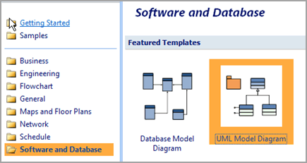
On the File menu, point to New, point to Software and Database, and then click UML Model Diagram.
-
In the tree view, right-click the package or subsystem in which you want to include a use case diagram, point to New, and then click Use Case Diagram.
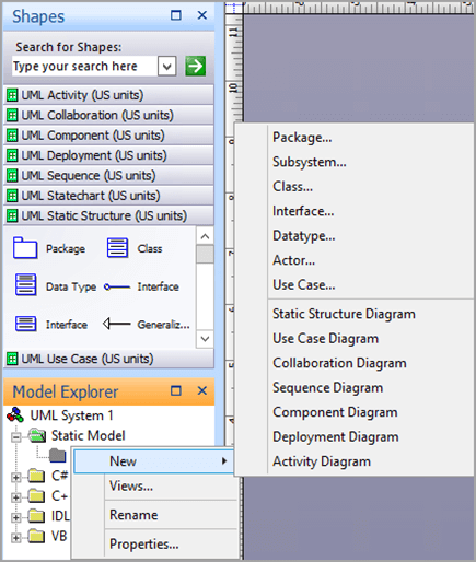
A blank page appears, and the UML Use Case stencil becomes the top-most stencil. An icon representing the diagram is added to the tree view.
Note: If the tree view is not visible, on the UML menu, point to View, and then click Model Explorer.
-
To indicate a system boundary in a use case diagram
-
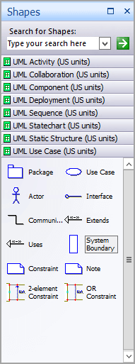
Drag a System Boundary shape onto the drawing page.
-
Double-click the System Boundary shape, and then type a new name for the system or press the DELETE key to delete the existing name. Click outside the shape on the drawing page.
-
To resize the system boundary, select the shape, and then drag a selection handle.
-
-
Drag Use Case shapes from the Use Case stencil and place them inside the system boundary, and then drag Actor shapes to the outside of the system boundary.
-
Use Communicates shapes to indicate relationships between use cases and actors.
To indicate a relationship between an actor and a use case
-
In a use case diagram, drag a Communicates shape onto the drawing page.
-
Glue one endpoint
 of the Communicates shape to a connection point
  on an Actor shape. Glue the other endpoint to a connection point on a Use Case shape.
 -
If you want to add an arrow to indicate the flow of information, do the following:
-
Double-click the Communicates shape, then, under Association, click the end you want to edit, and then click Properties.
-
In the Association End category, check IsNavigable, click OK, then click OK again.
-
Right-click the Communicates shape and click Shape Display Options. Under End options, select End navigability, and then click OK.
-
-
-
Use Uses and Extends shapes to indicate the relationships between use cases.
To indicate a uses relationship between two use cases
-
In a use case diagram, drag a Uses relationship shape onto the drawing page.
-
Glue the Uses endpoint without an arrowhead to a connection point
 on the Use Case shape that uses the behavior of the other use case.
 -
Glue the Uses endpoint (with an arrowhead) to a connection point on the use case being used.
-
Double-click the Uses shape to open the UML Generalization Properties dialog box. Add property values, and then click OK.
To indicate an extends relationship between two use cases
-
In a use case diagram, drag an Extends shape onto the drawing page.
-
Glue the Extends endpoint
 without an arrowhead to a connection point
  on the use case providing the extension.
 -
Glue the Extends endpoint with an arrowhead to a connection point on the base use case.
-
Double-click the Extends shape to open the UML Generalization Properties dialog box. Add the property values, and then click OK.
-
-
Double-click any shape (except the System Boundary shape) to open its UML Properties dialog box where you can add a name, attributes, operations, and other property values.
-
Save the diagram.
No comments:
Post a Comment