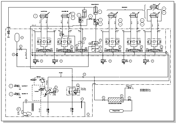
Create a pneumatic or hydraulic control system diagram
Create fluid power diagrams to document hydraulic or pneumatic control systems, such as those used in factory automation systems, heavy machinery, or automobile suspension systems.

-
On the File menu, point to New, point to Engineering, and then click Fluid Power.
This drawing type opens an unscaled drawing page in landscape orientation
 . You can change this setting at any time.
 -
Drag equipment and valve shapes onto the drawing page.
You can configure many shapes by right-clicking them.
-
Connect components using the Connector tool
 or connector shapes.
Use the Connector tool
-
Click the Connector tool
 .
. -
Drag from a connection point
 on the first shape to a connection point on the second shape. The connector endpoints turn red when the shapes are connected.
Use connector shapes
-
Drag a connector shape onto the drawing page.
-
Place the connector's begin point
 on the parent shape (the shape you're connecting from). Place the connector's end point
  on the child shape (the shape you're connecting to).
When the connector is glued to the shapes, the endpoints turn red.
-
-
Add text to shapes by selecting the shape and typing.
Most fluid power shapes have a control handle that you can drag to reposition text.
-
Add callouts and other reference notes by dragging shapes from Annotations onto the drawing page.
-
Shapes can have shape data. You can enter shape data and add new data to a shape.
Enter shape data
-
Select a shape, and then on the Shape menu, click Shape Data.
-
In the Shape Data dialog box, click in each cdata field and type or select a value.
-
No comments:
Post a Comment