Create a detailed network diagram by using external data in Visio Professional
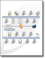
Creating a detailed network diagram with Microsoft Office Visio Professional 2007 is an effective way to design and document a computer network, as in the following illustration.

Using the Detailed Network Diagram template and the Data Link features, you can create a diagram that shows how equipment is logically or physically connected, add initial data to identify each shape, and then import and link external data to your network shapes.
Note: The Detailed Network Diagram template is included in Microsoft Office Visio Professional, but not in Microsoft Office Visio Standard. To find out which edition you have, click About Microsoft Office Visio on the Help menu. The name of the edition is in the top line of text in the dialog box.
What do you want to do?
Create a network diagram
-
On the File menu, point to New, point to Network, and then click Detailed Network Diagram.
-
From Network and Peripherals, drag a Ring network or Ethernet shape onto the drawing page.
-
From Computers and Monitors or Network and Peripherals, drag device shapes onto the drawing page.
-
Attach devices to the Ring network or Ethernet shape by using the shape's built-in connectors:
-
Click the Ring network or Ethernet shape.
-
Place the pointer over a control handle
 . When the pointer changes to a four-headed arrow, drag it to a connection point
  on one of the device shapes.
When the device shape is correctly connected to the Ring network or Ethernet shape, the connection point turns red, indicating that it is glued.
Tip: To hide an unused connector, drag the control handle
 back to the Ring network or Ethernet shape.
-
-
Add a legend to your network diagram:
-
From Network and Peripherals, drag the Legend shape onto the drawing page.
-
To configure the Legend shape, right-click the Legend shape, and then click Configure Legend on the shortcut menu.
-
To edit the text in the Legend shape, double-click the text that you want to change, and then type.
-
-
To add text to a network shape, click the shape and type. To move the text, drag the control handle
 .
.
Import external data about equipment into your drawing
-
On the Data menu, click Link Data to Shapes.
-
On the first page of the Data Selector Wizard, choose which of the following types of data sources you want to use:
-
Microsoft Excel Workbook
-
Microsoft Access database
-
Microsoft Windows SharePoint Services List
-
Microsoft SQL Server database
-
Other OLEDB or ODBC Data Source
-
Previously created connection
-
-
Complete the remainder of the wizard.
Note: If you choose an option other than an Excel workbook, Access database, or SharePoint list on the first page of the wizard, you may be temporarily diverted to the Data Connection Wizard in the course of completing the Data Selector Wizard.
Specific help is available for most wizard pages. To access Help, press F1 or click the Help button.
After you click Finish on the last page of the Data Selector Wizard, the External Data window appears with your imported data shown in a grid.
Note: The data that appears in the External Data window is a snapshot of your source data at the time of the import. You can update the data in your drawing to match the changes in your source data. However, you cannot update your data source by changing the data in your drawing. See the article Refresh imported data.
Add initial data to identify the equipment shapes
Before you can automatically link imported data to your network shapes, you need to add information to your shapes to uniquely identify each one. For example, if you add an asset number to each shape and you have a column for asset numbers in your data source, Visio can use that number to match the rows in the table to corresponding shapes in the diagram.
-
Right-click a network shape in your drawing, point to Data on the shortcut menu, and then click Shape Data.
Tip: Or you can select the shape, press ALT+D, and then press S.
-
In the Shape Data dialog box, type an asset number or other unique identifier into the appropriate field.
Note: Most Visio network shapes have a set of predefined shape data. If you want to use a shape that doesn't already have this shape data, you are prompted with a dialog box that asks if you want to define the shape data now. Click Yes. For information about how to fill out the Define Shape Data dialog box, see the article Add data to shapes.
-
Click OK, or press ENTER.
Automatically link external data to network shapes
-
On the Data menu, click Automatically Link.
-
Follow the steps in the Automatic Link Wizard.
Specific help is available for most wizard pages. To access Help, press F1 or click the Help button.
Your data appears in your shapes.
Note: You can customize the data that is displayed in your network shapes by using the Data Graphics feature. For information about how to use the Data Graphics feature, see the article Enhance your data with data graphics.
We can share this blog as a reference to anyone related to this topic. Thanks for sharing.
ReplyDeleteAWS Course in Chennai
AWS Online Course
AWS Course in Bangalore