Show size or dimensions of shapes in Visio
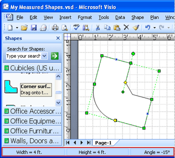
To see the dimensions, or measurements, of a shape, select it and look in the status bar below the Shapes window. The width, height, and angle are listed automatically. Or, view dimensions using one of the other methods described in this article.
To learn how to change the dimensions or angles of a shape using the Size & Position window, see Specify dimensions by using the Size & Position window.
Display measurements on the diagram page
If you have Visio Standard, you can display a shape's dimensions by using fields linked to the shape's height and width properties. For more information about using fields, see Use fields to keep displayed information current.
If you have Visio Professional, you can use dimension shapes to show sizes. Dimension shapes show the size of the shape they're glued to, and are updated automatically when you resize the original shape.
Dimension shapes are included in some templates, and you can open a Dimensioning stencil in any template.
To open a Dimensioning stencil
-
In the Shapes window, click More Shapes.
-
Point to Visio Extras, and then click Dimensioning-Architectural or Dimensioning-Engineering.
-
Drag a dimension shape to the shape you want to measure, and glue the ends of the dimension shape to the points you want to measure.
Note: To change measurement units, right-click the dimension shape and click Precision & Units on the shortcut menu.
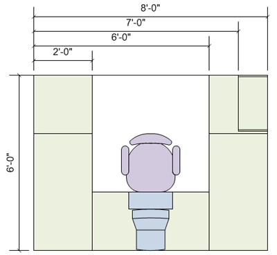
Example
If you have Visio Professional, the following procedure guides you through an example of how to use dimension shapes.
To use dimension shapes (an example)
-
Click the File tab, click New, click Categories, click Maps and Floor Plans, and then double-click Home Plan.
-
Click the title bar of the Garden Accessories stencil, and drag the Concrete pathway shape onto the drawing page.
You might need to scroll the list under Stencils to locate this stencil or others.
-
Drag the handles on the Concrete pathway shape to enlarge it.
-
Click the title bar of the Dimensioning - Architectural stencil, and drag the Horizontal shape to the drawing page above the pathway shape.
If you do not see this stencil in the list, follow the instructions in the preceding procedure, To open a Dimensioning stencil.
-
Drag the shape handle on the right side of the Horizontal dimension shape to the right edge of the pathway shape, until the green box appears indicating that the shapes are glued together.
-
Drag the shape handle on the left side of the Horizontal shape to the left edge of the pathway shape.
-
Drag the yellow diamond (
 ) that is on the right side of the dimension shape to a position above the pathway so that the dimension lines don't obscure the pathway shape.
What do you want to do?
View the overall width, height, and angle of a shape
-
Select the shape in your drawing.
-
Look at the status bar to see the width, height, and angle of the shape.
Display the width, height, and angle of a shape inside the shape
If you want to display the overall measurements of only a few shapes, you can quickly add measurement fields to shapes that have text boxes.
-
Click the shape that you want to add fields to.
-
On the Insert tab, in the Text group, click Field.
-
In the Field dialog box, in the Category list, click Geometry.
-
In the Field name list, click the measurement that you want to display.
Tip: To add units such as feet to the numbers, click Data Format, and then choose new units in the Data Format dialog box.
-
Click OK.
-
Repeat the steps for each field that you want to add.
Tip: To display the height and width with an x between them, insert the first field in the text box of the shape, and then type a space, type x, type another space, and then insert the second field.
Display the width, height, and angle of a shape next to a shape
Note: The data graphics features are available only in Visio Professional and Premium editions.
Data graphics provide a quick way to display the height, width, and angle of shapes as well as other shape data. This article describes how to display measurements.
-
On the Data tab, in the Display Data group, click Data Graphics.
-
Click Create New Data Graphic.
-
In the New Data Graphic dialog box, click New Item.
-
In the New Item dialog box, in the Data field list, click More Fields.
-
In the Field dialog box, in the Category list, click Geometry.
-
In the Field name list, click the measurement that you want to display, and then click OK.
-
In the New Item dialog box, in the Displayed as list, click Text.
-
Under Details, in the Label box, type a name for the measurement (such as Width or Height), and then click OK.
-
Repeat the steps for each measurement that you want to display.
-
In the New Data Graphic dialog box, click OK.
The new data graphic appears in the Data Graphics gallery, under Available Data Graphics.
-
Select the shapes in your drawing that you want to display measurements for, and then, in the Data Graphics gallery, click the data graphic that you created.
The new data graphic is applied to the selected shapes.
Display the measurements of parts of shapes

Note: The dimension shapes are available only in Visio Professional and Premium editions.
You can use dimension shapes to measure other shapes. When you glue a dimension shape to the shape that you want to measure, the shape's measurements are displayed on the dimension shape. The measurements are updated automatically as you resize the original shape.
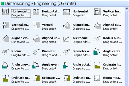
There are many dimension shapes, and each one measures a different aspect. You can get a good idea of what the different dimension shapes can measure by looking at the stencils, such as the Dimensioning - Engineering stencil.
To give you an idea of how dimension shapes work, the following procedure demonstrates how to use one of the dimension shapes to measure a pathway in a home plan.
-
Click the File tab, click New, click Maps and Floor Plans, and then double-click Home Plan.
-
Click the title bar of the Garden Accessories stencil, and drag the Concrete pathway shape onto the drawing page.
-
Click the title bar of the Dimensioning - Architectural stencil, and drag the Horizontal dimension shape to the drawing page above the pathway shape.
-
Drag the shape handle on the right side of the Horizontal dimension shape to the right edge of the pathway shape, until the red box appears indicating that the shapes are glued together.
-
Drag the shape handle on the left side of the Horizontal shape to the left edge of the pathway shape.
-
Drag the yellow diamond that is on the right side of the dimension shape to a position above the pathway so that the dimension lines do not obscure the pathway shape.
Note: To change measurement units, right-click the dimension shape and click Precision & Units on the shortcut menu.
What do you want to do?
View the overall width, height, and angle of a shape
-
Select the shape in your drawing.
-
Look at the status bar to see the width, height, and angle of the shape.
View the area or perimeter measurement of a shape
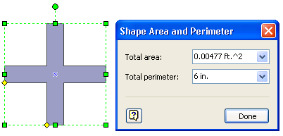
Note: The Shape Area and Perimeter dialog box is available only in Microsoft Office Visio Professional.
-
Select the shape in your drawing.
-
On the Tools menu, click Add-Ons, click Visio Extras, and then click Shape Area and Perimeter.
The Shape Area and Perimeter dialog box opens and displays the measurements of the shape.
-
To see the measurements in different units, select the units that you want in either the Total area box or the Total perimeter box.
Display the width, height, and angle of a shape inside the shape
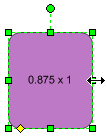
If you want to display the overall measurements of only a few shapes, you can quickly add measurement fields to the shapes' text boxes. If you have Office Visio Professional 2007 and you want to display the measurements of many shapes, you can save time by using data graphics, as described in the section Display the width, height, and angle of a shape next to a shape.
-
Click the shape that you want to add fields to.
-
On the Insert menu, click Field.
-
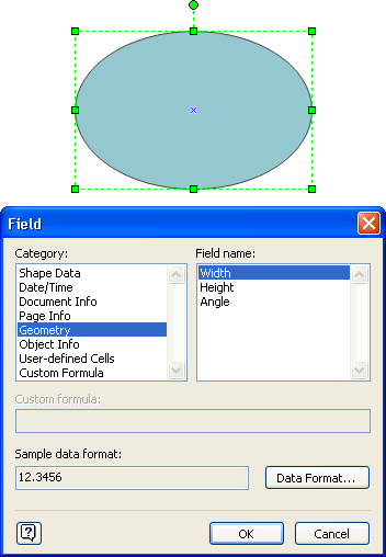
In the Field dialog box, in the Category list, click Geometry.
-
In the Field name list, click the measurement that you want to display.
Tip: To add units such as feet to the numbers, click Data Format, and then choose new units in the Data Format dialog box.
-
Click OK.
-
Repeat steps 2 through 5 for each field that you want to add.
Tip: To display the height and width with an x between them, insert the first field in the text box of the shape, and then type a space, type x, type another space, and then insert the second field.
Note: The measurements in fields update automatically when you resize a shape.
Display the width, height, and angle of a shape next to a shape

Note: The data graphics features are available only in Office Visio Professional 2007.
Data graphics provide a quick way to display the height, width, and angle of shapes as well as other shape data. This article describes how to display measurements. For information about how to make full use of data graphics, see Enhance your data with data graphics.
-
On the Data menu, click Display Data on Shapes.
-
In the Data Graphics task pane, under Create a new data graphic, click New Data Graphic.
-
In the New Data Graphic dialog box, click New Item, and then click Text.
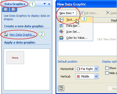
1. The Data Graphics task pane
2. The New Data Graphic command
3. The New Data Graphic dialog box with the New Item box and the Text command
-
In the New Text dialog box, under Display, in the Data field list, click More Fields.
-
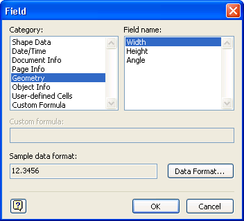
In the Field dialog box, in the Category list, click Geometry.
-
In the Field name list, click the measurement that you want to display, and then click OK.
-
In the New Text dialog box, under Details, in the Label box, type a name for your measurement (such as Width, Height, or Angle) and then click OK.
-
Repeat steps 3 through 7 for each measurement that you want to display.
-
In the New Data Graphic dialog box, click OK.
The new data graphic appears in the Data Graphics task pane, under Apply a data graphic.
-
Select the shapes in your drawing that you want to display measurements for, and then, in the Data Graphics task pane, click the data graphic that you created.
The new data graphic is applied to the selected shapes.

Display the measurements of parts of shapes

Note: The dimension shapes are available only in Office Visio Professional 2007.
You can use dimension shapes to measure other shapes. When you glue a dimension shape to the shape that you want to measure, the shape's measurements are displayed on the dimension shape. The measurements are updated automatically as you resize the original shape.
There are many dimension shapes, and each one measures a different aspect. You can get a good idea of what the different dimension shapes can measure by looking at the stencils. The figure below shows the shapes on the Dimensioning - Engineering stencil.
To give you an idea of how dimension shapes work, the following procedure demonstrates how to use one of the dimension shapes to measure a piano in a home plan.
-
On the File menu, click New, click Maps and Floor Plans, and then click Home Plan.
-
Click the title bar of the Furniture stencil, and drag the Grand Piano shape onto the drawing page.
-
Click the title bar of the Dimensioning - Architectural stencil, and drag the Horizontal dimension shape to the drawing page above the piano shape.
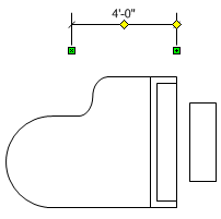
-
Drag the green shape handle on the right side of the Horizontal dimension shape to the right edge of the piano shape, until the red box appears indicating that the shapes are glued together.
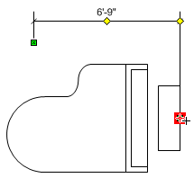
-
Drag the green shape handle on the left side of the Horizontal shape to the left edge of the piano shape.
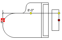
-
Drag the yellow diamond that is on the right side of the dimension shape to a position above the piano so that the dimension lines do not obscure the piano shape.
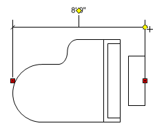
Note: To change measurement units, right-click the dimension shape and click Precision & Units on the shortcut menu.
No comments:
Post a Comment