Create a UML deployment diagram

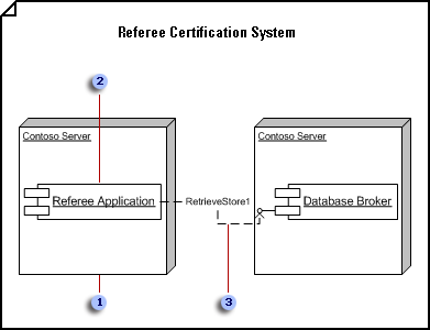
 In a deployment diagram, a node can represent a generic type or a specific instance.
 Place components and object instances within a node instance to indicate that the components and objects reside on the node.
 Dependencies connect components, sometimes through interfaces. You can use a stereotype to indicate the precise dependency.
-
On the File menu, point to New, point to Software, and then click UML Model Diagram.
-
In the tree view, right-click a package or subsystem in which you want to include the deployment diagram, point to New, and then click Deployment Diagram.
A blank page appears, and the UML Deployment stencil becomes the top-most stencil. The workspace displays 'Deployment' as a watermark. An icon representing the diagram is added to the tree view.
Note: If the tree view isn't visible, point to View on the UML menu, and then click Model Explorer.
-
Drag a Node shape onto the drawing page. Drag Component and Object shapes into the node. Drag a selection handle on the node to resize it.
Contain elements within a node in a deployment diagram
-
In a deployment diagram, drag a Node or Node Instance shape from the UML Deployment stencil onto the drawing page.
-
Double-click the node to add a name, attributes, operations and other property values.
-
Drag a corner selection handle to resize the node so it can accommodate the elements you want it to contain.
-
Drag Component, Component Instance, and Object shapes on top of the Node shape, and then connect the shapes with dependency relationships where appropriate.
-
Do one of the following:
-
Double-click each node. In the UML Node Properties dialog box, click Components. Under Choose the components which are deployed by this node, select the appropriate components, and then click OK.
-
Double-click each component. In the UML Component Properties dialog box, click Nodes. Under Choose the nodes which deploy this component, select the appropriate nodes, and then click OK.
Note: Do not group a node and the shapes it contains. If you need to move a node and the elements within it, drag a selection rectangle around the node to select all the shapes, and then drag them to the position you want.
-
-
-
Repeat step 3 until you have all the nodes you need.
-
Where appropriate, drag an Interface shape onto the drawing page and glue the endpoint without the circle to a component shape.
Add an interface to a class, component, or other element
-
In a static structurecomponent, or deployment diagram, drag the lollipop Interface shape onto the drawing page.
-
Glue the endpoint without the circle to a connection point
 on the class component, or other element.
 -
Double-click the Interface shape to add a name, operations, and other property values.
tiplist
You can also represent an interface with a rectangular Interface shape that resembles a class. Use this shape when you want to display a list of the interface operations.
To change the type of shape that displays for an interface, right-click the Interface shape and click Show as Class-like Interface or Show as Lollipop Interface.
-
-
Use Communicates shapes to indicate the relationships between nodes.
Indicate a communication association between nodes in a deployment diagram
-
In a deployment diagram, drag a Communicates shape from the UML Deployment stencil onto the drawing page.
-
Glue one endpoint of the Communicates shape to a connection point
 on the first node.
 -
Glue the other endpoint of the Communicates shape to a connection point on the second node.
-
Double-click the Communicates shape to add a name and other property values to the element and to its ends.
-
-
Use Dependency shapes to indicate the relationships between components and objects, and between components and other components' interfaces.
Indicate a dependency relationship between UML elements
-
Drag a Dependency shape from the UML Static Structure, UML Deployment, or UML Component stencil onto the drawing page and place it near the elements you want to relate.
-
Glue the endpoint with an arrowhead to a connection point
 on the element the other element depends on. Glue the endpoint without an arrowhead to a connection point on the element that depends on the other element.
 -
Double-click the dependency to add a name, stereotype, and other properties.
Tip: If you want to indicate a trace, refinement, usage, or binding dependency, you can use the Trace, Refinement, Usage, or Binding shapes from the UML Static Structure stencil.
-
-
Double-click any shape to open its UML Properties dialog box where you can add a name, attributes, operations, and other properties.
-
Save the diagram.
No comments:
Post a Comment